C - Code-Free MQTT-Devices Using Tasmota
Ever since creating SmoothMQTT, I was searching for a good code-free possibility to install and setup IoT devices. Then I found Tasmota and it is amazing.
For those who may have limited time and/or attention span, please find the TL;DR for a condensed summary of the information at the bottom of this page.
Disclaimer
Tasmota does not endorse SmoothMQTT or has in any way compensated me for including it here. Frankly, they probably don't even know about SmoothMQTT. I just love this Framework and believe it contributes to the same vision of lowering the entry barrier for working with IoT devices, just like SmoothMQTT does.
What is Tasmota
If you're interested in building and managing your own smart home or tinkering with smart devices for your games without coding Tasmota has you covered. Tasmota is an open-source firmware that can be used to control various types of smart home devices such as lights, outlets, and sensors. It's a popular choice among smart home enthusiasts and DIYers because it is easy to use and highly customizable. With Tasmota, you can configure your smart home devices to behave in specific ways based on certain triggers or conditions. For example, you can set up a rule to turn on the lights in your living room when you open the front door, or you can create a timer to turn off your coffee maker after it's been on for a certain amount of time. The possibilities are endless, and Tasmota makes it easy to get started with your own smart home projects.
This manual will focus on the Tasmota basics and show you how to connect and use Tasmota smart devices together with SmoothMQTT. Therefore, after reading through these instructions, you should be able to use data from a simple sensor like for example BMP180 (temperature and humidity) or similar sensors, as well control for example Tasmota sockets (switch on or off, depending on your Unity scene).
Setting up Tasmota:
Chrome users
If you happen to use the Chrome browser, there is a very convenient way of flashing your ESP32 with Tasmota firmware.
- Connect it with USB to your computer
- Go to https://tasmota.github.io/install/
- Follow the instructions on screen for flashing Tasmota
Other browsers
Here is a step-by-step guide to setting up Tasmota on a blank ESP32 devkit using the commandline:
- Download the Tasmota firmware file from the Tasmota website. Make sure to download the correct version for your ESP32. If you do not have specific requirements, go for the tasmota32.bin file.
- Install esptool with
python3 -m pip install esptool. Note: you will need Python3 installed on your system. The official documentation can be found here. - Connect the ESP32 devkit to your computer using a micro-USB cable.
- Find out the port of your device. On windows you can check the device manager, the port usually has the format COMX (where X is a number). On macOS the port is usually called /dev/cu.usbserial.X (where X is a number), find it with
ls /dev/ | grep "usb"on the Terminal. - Open a Terminal in your Downloads folder
- [optional] Run
python3 -m esptool -p [name of your port] read_flash 0x00000 0x100000 fwbackup.binto create a backup of the current firmware - Run
python3 -m esptool -p [name of your port] erase_flashto delete the ESP memory - Run
python3 -m esptool -p [name of your port] write_flash 0x0 tasmota32.binto write the Tasmota firmware onto your ESP32. Note: For other boards it might be different, if in doubt check the Tasmota documentation.
At this point, your ESP32 is now running Tasmota and is ready to be configured and used to control your smart home devices. In the next section, we'll cover the steps for setting up and accessing the Tasmota web interface.
Configuring Tasmota for the first time:
Now that you've set up Tasmota on your device, you'll probably want to customize the settings to suit your needs. In this section, we'll go over the various options available in the Tasmota web interface and how to use them to configure your Tasmota device. The official Tasmota manual on how to configure the device can be found here under the tab Web-UI.
Configuring WiFi
- Connect your ESP to a power source.
- On the first start, it will create a wireless access point. The name will be something like tasmota_XXXXXXX-YYYY
- Use some device (in this example a phone) to connect to this WiFi access point.
- Wait for the captive portal to open or if it doesn't go to http://192.168.4.1 in your phone browser.
- Here you can enter (or click if listed) your WiFi network name (SSID) and password to connect your Tasmota device to your local network.
- Once it is connected, it will show you the IP address of the ESP in the browser. It depends on your network, but might look like 10.0.0.123. Write that down.
- Connect your phone back to the normal WiFi.
Now your ESP is successfully connected to your WiFi. Continue with configuring the MQTT part.
Configuring MQTT
- Go to http://<ip>, e.g. http://10.0.0.123
- Enter the Configuration -> MQTT menu (see Screenshot)
- Set Host to the MQTT broker address
- Set the client ID in "client"
- Set Username and password if applicable.
- Set the topic to something that helps you remember it (e.g. sensors/livingroom/temp_hum)
- Leave full_topic as is, an explanation follows below
- Click "Save" to apply your changes.

That's it! You've now configured Tasmota for the first time and are ready to start using it to control your smart home devices. In the next section, we'll discuss how to use Tasmota together with SmoothMQTT to control your devices.
Examples
Measuring temperature and humidity with BMP180
To use a BMP180 sensor with Tasmota, you'll need to connect it to the ESP32. Follow the wiring diagram provided with the BMP180 to connect the sensor to the ESP32 using the GND, VCC, SDA, and SCL pins. Please make sure the ESP is not powered, before you start wiring anything. Typically SDA and SCL connect to pin 21 and 22 respectively.
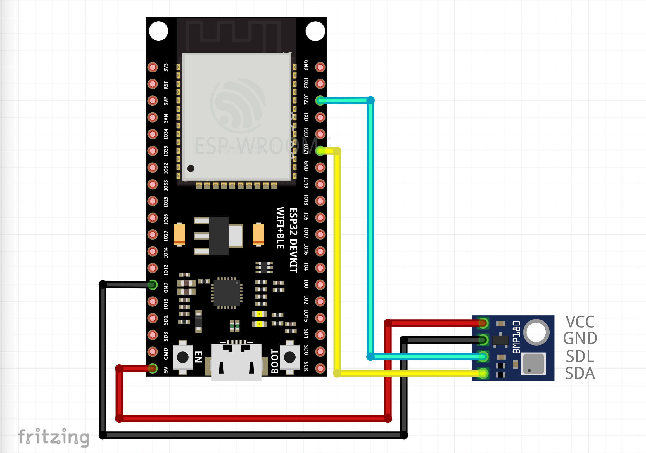
wiring
Double check the pins, as the pinout of your BMP180 board or your ESP32 may differ. Wiring the wrong pins can destroy your boards.
Once the BMP180 is connected to the ESP32, power it again and go to the web interface. You'll need to configure Tasmota to recognize the sensor. Therefore, in the Tasmota web interface, go to the "Configuration" tab and select "Configure Other". Scroll down to the "GPIO21" and "GPIO22" options and enter the "I2C SDA" and "I2C SDL" respectively. Then, click "Save" to apply your changes.
Now that the BMP180 is connected and configured, you can use Tasmota to access the temperature and humidity readings from the sensor. You can display the readings on the Tasmota web interface, or you can use MQTT to send the readings to a different device or service. For example, you can set up a rule to send an alert to your phone if the temperature exceeds a certain threshold, or you can create a timer to send the humidity readings to your game on a regular time interval. However, we'll not discuss Rules in-depth.
Below the other example is a guide on how to use data from this configured tasmota device
Controlling a smart socket
If you want to switch power on and off for example on a fan, you can use pre-flashed smart sockets which use tasmota. In Europe Nous A1T is a good choice. I'm not affiliated with them and I don't know if they ship worldwide though.
Configure the smart socket just like the ESP32 above by connecting to it and setting up WiFi and MQTT. Afterwards, you can use the Tasmota WebUI to toggle the socket.
Controlling tasmota devices with SmoothMQTT
First, make sure you have the SmoothMQTT plugin installed in your Unity project. You can find it on the Unity Asset Store or download it from the SmoothMQTT website.
Once you have SmoothMQTT installed, you'll need to add the JsonSubscriber component to a gameobject in your scene. You can do this by selecting the gameobject, then going to the menu "Tools/SmoothMQTT/Receive/Json Payload". This will add the JsonSubscriber component to the gameobject, which you can use to receive messages from the Tasmota device.
To configure the JsonSubscriber component, you'll need to enter the correct topic that the Tasmota device is publishing to. This will typically be in the form of "stat/[topic name]/[reading]", where [topic name] is the name of your Tasmota topic defined in the config and [reading] is the type of message you want to receive. For example, you might use a topic like "stat/livingroom/socket1/power" to receive power status messages from a Tasmota-powered socket in the living room. To access the aforementioned temperature and humidity sensor, you would subscribe to "stat/livingroom/temp_hum/status10"
Why status 10?
Tasmota allows for different commands to control what kind of status the ESP will return upon being polled for reading. Number 10 simply is the format, where the ESP returns a time stamp and all sensor readings available (see tasmota Docs for reference). To set up a polling topic, simply enter the topic and payload that you want to receive updates for in the "Poll Topic" and "Poll Payload fields and enter the time interval in the "Poll Interval" field. To get this Status10 reply mentioned above, the poll topic is "cmnd/livingroom/temp_hum/status" and the payload is "10". So giving a tasmota device a command is prefixed with "cmnd/" and reading the returned values is prefixed with "stat/".
Once you've set up the JsonSubscriber component with the correct topic and optional polling settings, you need to tell the component how to find data in the json that is returned. Check the manual entry JsonSubscriber for instructions.
To control the smart socket from example 2, just send a regular MQTT message to topic "cmnd/livingroom/socket1/power" with the payload "on", "off", or "toggle"
Overall, using SmoothMQTT in Unity to connect to a Tasmota device is a simple and straightforward process. With just a few clicks and a little bit of configuration, you can easily integrate Tasmota into your Unity projects and use it to control and monitor your smart home devices. Despite the fact tasmota rules will bring you a lot of possibilities to react to the environment, it is perfectly possible to create engaging experiences without writing code when using SmoothMQTT.
Imagine for example a VR experience, where the player enters a triggerzone (mountain summit for example) and in their room the fan socket switches on and provides wind to add to player immersion. Imagine infrared bulbs to support the illusion of entering a desert. Imagine a heart rate sensor's readings open certain doors in a dungeon crawler. Build a custom hardware for your trade fair booth. The possibilities are endless.
Conclusion
With this appendix you will be able to integrate most I2C or typical arduino sensors into your SmoothMQTT app. You will be able to control devices or monitor them. You can use the sensor readings to control the flow of your game, even switch scenes when certain events happen. And last but not least, you can build custom hardware that is easily integrated into your experience, as all the MQTT components provide UnityEvents to react to MQTT messages.
TL;DR
For custom sensors:
- Connect your Computer via USB with an ESP32/8266 devkit
- Go to https://tasmota.github.io/install/
- Follow the instructions to install the default version
- Connect the sensor to GPIO pins and remember which ones
Checkout https://tasmota.github.io/docs/Getting-Started/ for more information
For shelf-bought Tasmota devices or the custom ESP after the previous steps:
- Power the device.
- Look for a new wifi accesspoint (usually tasmota-XXXXXX) and connect
- If it does not open a captive portal automatically, open a browser at http://192.168.4.1
- On the page enter your WiFi credentials to allow the ESP to connect to your internal network.
- After connection you're either redirected or presented with an IP address (in your local network) open this address in your browser.
- Go to configuration->MQTT and set your host (IP of the MQTT broker), user/password if applicable, and a topic
::: Note
The topic set here is really usually the device name, because MQTT topics are auto-generated from these. So the topic office_temperature1 would lead to e.g. stat/office_temperature1/power or office/socket/fan (yes slashes are valid here) would yield e.g. cmnd/office/socket/fan/power
:::
Checkout https://tasmota.github.io/docs/MQTT/ for more information on configuring MQTT with tasmota.
- Once saved, your tasmota-device will send telemetry data in certain intervals (configuration is somewhere in the WebUI) and can also be prompted for data.
- Sending a message to cmnd/device-topic/command tells the device to do something
- stat/device-topic/Something will yield data
- The most important command for sensors is
cmnd/device-topic/statuswith payload10this will tell the Tasmota device to publish its data tostat/device-topic/status10. Data will be JSON formatted. - The most important command for smart power outlets is
cmnd/device-topic/powerwith a payload of eitheron,off, ortoggle
For everything available commands, check https://tasmota.github.io/docs/Commands/#commands-list
Personal support for Tasmota is limited
Please be aware that these instructions are provided free of charge to connect hardware to your SmoothMQTT app without having to code in C++ or python. This also means, however, there will be no unpaid email support for troubleshooting tasmota. Support is limited to SmoothMQTT and its associated components. For questions about Tasmota, please refer to the usual sources of help such as the Tasmota Docs, Stack Overflow(make sure to use tag tasmota), or Reddit.